Gas Well Liquid Loading
What is gas well liquid loading?
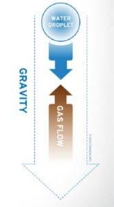
- An accumulation of fluids in the tubing
When does gas well liquid loading begin?
- Gas flow rate insufficient to overcome gravity
- Point where both forces are equal is the critical velocity
What are the consequences of gas well liquid loading?
- Once the hydrostatic head is equal to reservoir pressure, no production will occur
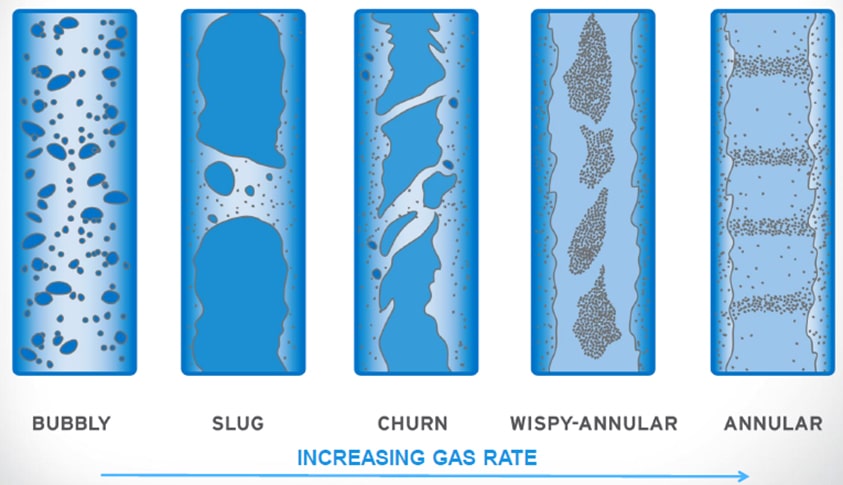
Flow Regimes of Vertical Wells
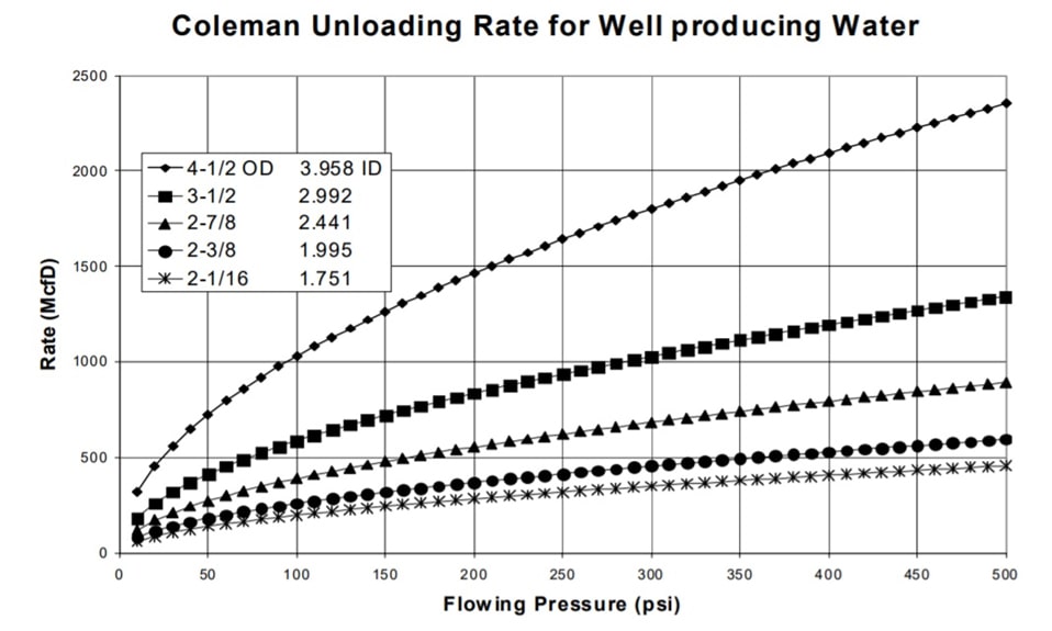
Critical Velocity
(calculation based on work done by Turner et al. or Coleman et al.)
p = Tubing pressure
ρ = Liquid density
C = A constant, depending on pressure, fluids, and surface tension
ρ = Liquid density
C = A constant, depending on pressure, fluids, and surface tension

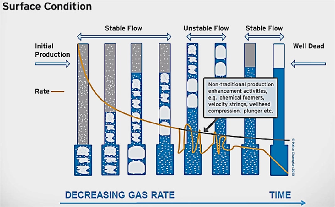
Signs of Liquid Loading
- sharp drops in the cumulative production decline curve
- the onset of liquid slugs in the surface facilities
- abrupt changes in the flowing pressure gradient
- low temperature spikes at the wellhead
- declining water production or condensate-gas-ratio
- the onset of liquid slugs in the surface facilities
- abrupt changes in the flowing pressure gradient
- low temperature spikes at the wellhead
- declining water production or condensate-gas-ratio
History of a Gas Well
Artificial Lift Options
Mechanical
- Rod Pumps
- Submersible Pumps
- Hydraulic Pumps
- Plungers
- Gas Lift
- Velocity Strings
- Compression
- HOOS
- Rod Pumps
- Submersible Pumps
- Hydraulic Pumps
- Plungers
- Gas Lift
- Velocity Strings
- Compression
- HOOS
Chemical
- Liquid Foaming agents
- FALL
- Liquid Foaming agents
- FALL
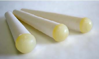
FALL Sticks
FALL sticks in general are designed to foam the water in the tubing, therefore allowing the formation pressure to unload the fluid from the well. Natural gas bubbling through the water-column, produces foam which can help remove water from watered-up gas wells.

FALL Design Considerations
Thermal Stability
- Surface
- Down-Hole
Compatibility
- Metallurgy
- Fluids
- Chemical
Oil/ Condensate/ Water Ratio
Regulatory
- Environmental
- Logistics
System completion
- Production Increases
- Emulsion Tendencies
- Excess Foaming
- Chemical Feed Options
FALL Application
Surfactants typically applied to aqueous systems
- Reduce surface tension
- Decrease relative density
- Increases elasticity
Allows gas/liquid dispersion at a lower gas pressure
- In the lamella condensate is trapped
- Reduce surface tension
- Decrease relative density
- Increases elasticity
Allows gas/liquid dispersion at a lower gas pressure
- In the lamella condensate is trapped

How much FALL is required?
Salinity of water
- Salinity increases water specific gravity
- Charge neutralization
Gas flow rate
- Closer to critical is less chemical demand
- Flow speed is more important then composition
Contaminants with defoaming action
- Solids
- Hydrocarbon condensates
- Salinity increases water specific gravity
- Charge neutralization
Gas flow rate
- Closer to critical is less chemical demand
- Flow speed is more important then composition
Contaminants with defoaming action
- Solids
- Hydrocarbon condensates
Disruption of inter-facial film structure
- Displacement of stabilizing surfactant – i.e. by corrosion inhibitor
Spontaneous spreading of oils
- Low surface tension liquids
- Positive spreading coefficient
Physical rupture of lamella
- Waxy or hydrophobic particles
- Oil droplets
- Displacement of stabilizing surfactant – i.e. by corrosion inhibitor
Spontaneous spreading of oils
- Low surface tension liquids
- Positive spreading coefficient
Physical rupture of lamella
- Waxy or hydrophobic particles
- Oil droplets
Procedure
1. Shut-in the well and drop sticks through a lubricator.
2. Wait some seconds/minutes or until sticks contact top of fluid.
3. Slowly return well to normal production.
4. Repeat procedure if or when it becomes necessary.
- In high rate wells (after sticks) flow well at about 25% of pretreatment rate for 30 minutes or until foam reaches surface then return to normal rate.
- In shallow or low rate wells, leave well flowing while dropping sticks if possible.

Recommended Wells
- Gas flowing wells with water/oil hold up for efficiency improvement
- Gas shut-in wells with water/oil loading and natural gas bubbling through the liquid column
- Gas shut-in wells with water/oil loading without any gas flow
- Gas shut-in wells with water/oil loading and natural gas bubbling through the liquid column
- Gas shut-in wells with water/oil loading without any gas flow
